WWW.RTTY.COM History Hall
|
ITT
Creed Model 444 Introduction
Construction Robust "unit construction" for easy maintenance and accessibility. Each major unit is carried on its own casting or frame, and is secured by no more than four screws. Where appropriate, eg on the motor unit, the screws have been made captive. Abutments are provided to locate the units accurately. All units are interchangeable without need to re-adjust except in isolated cases. Individual components have been designed for easy assembly with the minimum number of adjustments. Units can be dismantled and then reassembled without the need for readjustment. The number of different fabricated parts is approximately 1,250 for a basic transmitter/receiver version of the machine fitted with a synchronous motor. A further 160 parts are involved in the Tape Reader unit, and 220 parts in the Tape Punch unit. Speeds The machine is designed for 50 Baud and 75 Baud operation, ie 66 and 100 words per minute respectively. Conversion from 50 Baud to 75 Baud operation is by changing motor and hours counter gearing. This conversion can be carried out without removing the motor or disturbing adjacent units. Receiving Electromagnet and Orientation The standard polarised receiving electromagnet is designed to respond to double-current signals, but can be provided with a single-current to double-current converter. Manual orientation adjustment determines the selection instant over +/- 60% of a code element length. The scale is calibrated to read receive margin directly. Alphabets Printing in all common Indo-European languages is possible up to a maximum of 56 graphics on two-shifts. Semitic languages such as Hebrew and cursive scripts such as Arabic, both involving a right-to-left type basket traverse action, can be catered for. Non-feeding type bars carrying ‘accents only’ are possible. Optionals The basic Model 444 machine consists of a 5-unit, 50 Baud or 75 Baud receiving mechanism fitted with a 3-row or 4-row keyboard, a friction feed platen, an end-of-line warning lamp, the two-colour printing faciliity, a motor hours counter and motor ‘on-speed’ contacts. Optional units and facilities that can be fitted to the basic machine include an answer-back facility, a Tape Punch unit, a Tape Reader unit, an automatic power switch, a dual purpose friction/sprocket feed platen, single double/current converter, paper-low contacts, a code recognition unit (stunt box), and right to left direction of printing for non Roman alphabets. The machine can be supplied as a receiver with tape punch keyboard, or as a receiver only. Dimensions and Weight External overall
dimensions of the machine in its sound-reducing cover are: Line Current and Margin Line current for the polarised electromagnet working on double current signals is 20mA (80+80V) with wave shaping components (3.9K shunted by 4mF) in series and a surge limiter (1mF + 1.2K) in parallel with the electromagnet. These components are now included in non-BPO double current machines but can be disconnected when not required. Single-current working (single-to-double current converter and special coil in electromagnet) will require 30 to 45mA with a line voltage of 50 to 120V. The receive margin is at least +/- 42% at 50 Bauds, and +/- 38% at 75 Bauds. Signal Divide The transmitters associated with the keyboard and with the tape reader unit are both designed for 7-1/2 unit operation. The teleprinter receiver is designed to accept 7 or 7-1/2 unit signals at 50 Bauds, and at 75 Bauds. Circuits Desks, tables or
plinths to mount the Model 444 can be supplied equipped for Telex, Private Wire
or a variety of special uses such as concentrators, broadcast sets etc. to suit
the available transmission paths and required operating facilities; also as
punched tape editing sets or data loggers. The facilities provided on four
typical terminal sets are given below: Local Record Electrical local record of double-current circuits is obtained by an automatic send-receive switch that connects the send line to the electromagnet for the duration of each transmitting cycle. Incoming signals are connected to the electromagnet by the send-receive switch. Single-current circuits obtain local copy by the inclusion of the receive electromagnet coils in the loop circuit. In both these modes an accurate local copy is proof of accurate transmission. Drive Transmitting and receiving mechanisms are driven by a single electric motor. Receiver employs three cam shafts (selector, main receive cam shaft, and type carriage feed shaft) each making half a revolution for each character. The keyboard transmitter has a single cam shaft which, for maximum accuracy, makes one complete revolution for each transmitted character. Both ratchet and friction type of clutch is used on the machine. The ratchet clutches incorporate a friction-driven element which provides the homing torque, helps to equalise the idling/running load, and reduces the impact when the drive is engaged. Motor Range Synchronous motors for 50Hz (3000 rpm) and 60Hz (3600 rpm) supplies, and any single voltage in the range 110-125V (5-volt steps), 200-250V (10-volt steps). Power consumption is approximately 80 watts. Series wound, 3750 rpm, AC single-phase governed motors for any single voltage in the range 100-125V (5-volt steps), 200-250V (10-volt steps), at 40, 50 and 60Hz. Series wound, 3750 rpm, DC single-phase governed motors for any single voltage in the range 100-125V (5-volt steps), 200-250V (10-volt steps). Power and Signaling Connections Separate captive cables are provided for motor power (3-way), and signaling circuits (32-way) Painton series 159. Provision for an additional 12-way plug and captive signals cable for code recognition contacts, if capacity of standard cable is exceeded. Electrical connections from the base tray, in which the power and signaling cables terminate, to the teleprinter mechanism are made via a 50-way Cannon type or 50-way Carr fasteners jack-in connector for the signals wiring, and a 6-way Painton Multicon connector (with twin earth pins) for the motor power supplies. Power supply from the teleprinter main base to the motor unit is via another 6-way Painton Multicon connector. The signals and motor connectors are located at the rear of the machine main base adjacent to the motor gearing. Maintenance Routine maintenance for 50-Baud machines will consist of inspection, cleaning, and lubrication after each 1000 hours of operation, or at intervals of one year, whichever is earlier. The overhaul interval is 5000 hours or 5 years, whichever is earlier. Maintenance intervals for 75-Baud working are to be 500 hours initially, with overhaul at 3000 hours or 3 years. All lubrication points requiring attention at the routine maintenance interval can be reached without dismantling. Only two lubricants: a light oil and a grease will be required. It will not be necessary to re-lubricate shielded motor bearings as the original lubricant inserted by the bearing manufacturer will last until the bearings are replaced at 5000 hours. All field maintenance can be carried out with common tools. Gauges will be available to simplify certain adjustments. Main cover and lid are secured to the base tray by two Oddie clips which require a quarter-turn with a screwdriver to release them and so enable the cover to be lifted off. The release of two sliding latches, and the disconnection of the internal power and signals plugs at the rear of the main base, enables the complete receiving and transmitting mechanisms to be lifted out of the base tray, while the input sockets and their cabling remain clamped inside the tray. Printing Mechanism The printing mechanism
of the Model 444 employs a moving typewriter-style type basket, and a stationary
platen unit which bears the paper roll. The type basket can hold up to 28 type
bars each carrying two characters, so giving a maximum capacity of 56
characters. A type bar is selected by allowing it to drop into a slot across an
arrangement of five castellated comb bars carried on the type basket carriage
unit and controlled by five vanes which are pivoted on the frame of the machine.
These vanes are in their turn controlled by the selection mechanism and the
incoming signals which it registers. The downward movement of the selected type
bar brings it into the path of a print bail which lifts the bar out of its
basket and so impresses the type against the ribbon to create an image on the
paper. Each character is printed as soon as it is received and the whole
printing line is visible while it is being printed. The case shift action is
obtained by raising the rod on which the type bars pivot so as to bring the
letters to the printing line, and by lowering the pivot again to bring figures,
symbols, and punctuation marks to the printing line. Printing is
through a half-inch wide typewriter ink ribbon which is wound on a
flanged spool of the type used on Creed Model 47 and Model
Seventy-five machines. The European standard typewriter spool DIN
2103 can also be used. The automatic ribbon feed changeover
mechanism will be operated by either a plain or eyeleted ribbon. A
mechanically operated automatic two-colour printing facility is
standard; transmitted copy normally being printed in red, and
receive copy in black. Stationery British, European and American paper rolls, both in their normal and reverse-wound forms, can be accommodated inside the sound-reducing cover. Maximum width for paper rolls is 8-1/2 inches (216mm). Maximum diameter of roll is 5 inches (127mm). Paper guide can be set by the operator to accept either 8.3 inch (210mm) or 8-1/2 inch (216mm) wide paper. Provision for external paper supply, and for sprocket-feed printed stationery. Machine can be fitted with a friction-feed platen, or with a dual-purpose friction/sprocket feed platen with retractable pins which is capable of being set to accept either plain paper or marginally-punched printed stationery. Platen units can be interchanged without dismantling other units from the machine. An external knob is provided to turn the platen and so advance the paper. Platens will accept friction-feed paper, either single-ply or up to 6-ply, with or without interleaved carbon sheets, and also carbonless multi-plies such as NCR paper. Print force is adjustable by mechanic and can be set to print up to six carbon copies. The dual purpose friction/sprocket feed platen is adjustable laterally to enable printing to take place in the middle of ruled columns on printed stationery. Three degrees of line feed by operator setting: 1/6 inch, 1/4 inch, and 1/3 inch, ie 4.23mm, 6.35mm, and 8.46mm respectively. The standard line length is 69 characters when the machine is fitted with a 70 toothed feed rack. Using 8-1/2 inch (216mm) paper the left hand margin is 0.75 inch (19mm) minimum from the edge of the paper to the centre line of the first character. The right hand margin is 0.95 inch (24mm). Other line lengths and margins using 8 -1/2 inch (216mm) paper are shown in the table.
Cover A three-piece metal
cover consisting of a base tray, a cover unit proper, and a counterbalanced lid
totally enclose the teleprinter mechanism and so reduce machine noise to a
minimum. The Tape Reader unit, the Tape Punch unit, an 8-inch diameter tape
reel, and a paper roll up to 5-inch diameter can all be accommodated within this
cover. The fitting of the Tape Reader and Tape Punch units only affects the
keyboard mask, which is readily interchangeable. Receiver-only applications are
satisfied by using a cover with the keyboard projection omitted. All three
sections of the cover which together weigh about 25 pounds, are aluminum
pressure die castings some 1/10 inch thick, and are lined with sound-reducing
plastic foam to give good noise insulation. The joints between the tray and
cover, and between the cover and lid are sealed with a rubber strip. The lid is
lightly spring-loaded towards the closed position, and is also stable in the
fully-opened position to give easy access to the tape reel, paper roll and
ribbon. Operators Manual Controls Keyboard: Maximum of 59 key buttons, plus two shift pads and a space bar Platen Controls: Platen
pressure ON/OFF control lever Functional Keys: Tape Punch Unit: Tape Reader Unit: Note 1 Run-out occurs
on the last key depressed, ie to start continuous transmission, depress the
selected, release it, and then depress the run out key. A range of 3750 rpm AC, and DC, governed motor units has been designed. As these units contain all the associated electrical equipment such as governing resitor, on-speed relay, and radio interference suppression components, and plug directly into the main base wiring, it is a simple operation to exchange a motor unit, or substitute one of a different type or voltage. The motor unit also contains the micro-switch associated with the automatic motor switch facility. This switch is operated by a lever from a mechanical time delay mechanism located on the teleprinter main base. The motor and its governor are protected by a metal cover which is force ventilated through louvres at the rear of the base tray. This cover completely encloses the motor and governor, and is retained by a single screw; live surfaces such as brush boxes, which would otherwise be exposed when the main cover is removed, are protected by individual plastic covers. In addition to reducing radio interference and noise, and preventing accidental contact with rotating parts, this overall cover prevents brush dust from finding its way on to the teleprinter mechanism and also prevents the motor ventilation system from drying out the lubricants. Governed motors will reach correct operating speed within 1 second at normal temperatures and nominal supply voltage. A centrifugal governor (see section headed ‘Governor’) compensates for temperature variations and for supply voltage variations of +/- 10% holding motor to within +/- 0.1% of the correct speed. Speed remains stable within +/- 0.5% over 1000 hours of continuous running. Brush life averages 2000 hours when the machine is operating at 50 Bauds. Brushes are similar to those used on Creed Model Seventy-five but are longer (3/4 inch (19.1mm) effective) and have a greater working area. Each brush is linked to the power supply by an insulated pigtail, and is held against the 45-segment commutator by a spiral spring designed to maintain almost uniform pressure as the brush shortens. Brushes are held in brass boxes carried on an adjustable plastic moulding and are sited so that the brushes trail. The effect of commutator rotation, brush spring pressure, and the offset positioning of the brush boxes combine to press the brushes against the side of their boxes so reducing vibration and sparking. Bearing life of 10,000 hours fixes the motor overhaul interval during which operation the commutator will need resurfacing. The two double-shielded ball bearings (British Standard type BRL 012) used in the motor are lubricated by the manufacturer and do not require any further attention until the 10,000 hour interval at which they are replaced. A manually-reset current overload protection device is provided as standard equipment. Resilient rubber mountings located between the main motor framework and its cradle help to reduce motor noise and vibration. A black and white 8-segment strobe disc viewed through a 125 dvs (250 cps shutter speed) tuning fork is provided as a visual speed check. Motor insulation standards are to British Standard 2757 Class E. Synchronous Motor Capacitor-start, capacitor-run motor units constructed and ventilated as governed motors described above, i.e. unit contains associated electrical equipment, microswitch, overload protection, etc. Absence of brushes enables motor overhaul interval to be extended to 10,000 hours at which time the bearings are replaced. Insulation, resilient mounting, bearings, and other applicable data as for governed motors. The motor reaches the synchronous speed within 1 second. The space previously taken up be the centrifugal governor is now occupied by a fan. ‘On-speed’ contacts are provided as part of the motor. Governor A centrifugally-operated governor similar in design to those used on previous Creed teleprinters is employed. This device holds the motor speed constant to within +/- 0.1% of nominal in the face of supply voltage variations of +/- 10%. The governor spring is anchored on a bi-metallic bar which flexes to compensate for the increase in length of the spring as the motor temperature rises. The manually set speed-adjustment screw on the governor spring anchor is electrically insulated from the main supply whatever the position of the governor contacts. The governor contacts are tungsten and are 1/4 inch (6.35mm) in diameter. Fins on the outside of the plastic governor cover act as a fan to force air over the motor windings and commutator. Keyboards Code selection by action of plain (ie uncontoured) keybars on an arrangement of castellated comb bars whose associated parallelogram linkages slide to the left or right depending upon coding. 3-row or 4-row full or partial shift lock keyboard arrangements are possible. The basic design is for a 63-slot board with 59 key positions plus two shift keys and a space bar. The slots for the shift keys and the space bar cannot normally be used for additional keys because of the ‘cut-out’ in the standard mask. The standard 4-row layout will have 57 operating keys and three pads (ie rectangular-shaped keys) for space, letter shift and figure shift. This layout includes two spare positions which are normally filled by non-operating key bars bearing square flat-topped key buttons which fill up the keyboard mask opening. The maximum number of operating keys for a 4-row layout is therefore 59 keys plus 3 pads. There will also be a condensed 4-row layout with 44 keys and one pad. The 3-row layout will have 33 keys plus 1 pad. Pitch of keys is 3/4 inch (19.1mm) horizontally and vertically. Slope is 15 degrees. Average key pressure is 8 ounces. Key stroke is approximately 3/16 inch on the top row of keys, and approximately 5/16 inch on the space bar. The individual key buttons are 5/8 inch in diameter. Two basic versions of the keyboard mask are available: the first a plain mask with no apertures for tape units, the second with two apertures, one for the Tape reader, the other for the Tape Punch. Each of these masks will have a middle aperture to suit the key button arrangements. When the ‘Here is’ key is not required a plastic plate conceals the hole in the mask. The standard keybuttons will normally be matt black injection-moulded plastic and will have their white characters pre-formed and cast into them at the moulding stage. This method of manufacture ensures that the legibility of the key tops will not be affected even by prolonged use. Alternative colours, in both keybuttons and their characters, can be provided. The characters on a key can be in one colour, and the keybutton itself in another colour. For example, white characters on a red button or red characters on a black button. Special ‘organ-type’ keys control the Tape Reader and the Tape Punch, and also give a direct manual control of some machine functions, protrude through horizontal slots in the front face of the keyboard mask immediately above the keyboard. These keys are grouped according to their use and all are within easy reach of the operating position. For English speaking users these keys will carry plain-language legends such as PERF ON, and RUN OUT. Organ type keys have been produced with their legends in certain foreign languages. As an alternative, a range of keys have been designed which carry the internationally-used symbols which indicate the purpose of each key diagrammatically, and so avoid the need for alternative keys to cater for foreign language machines. A storage keyboard for the Model 444 is not envisaged at present. Transmitter (Keyboard) The Model 444 has a single changeover contact, cam-controlled, striker transmitting mechanism which is capable of generating accurate double-current signals or, by a simple readjustment, bias-free single-current signals. An automatic send-receive switch is provided for operation of half-duplex or 2-wire circuits. The transmitting mechanism is designed for long-term stability, and to be easily adjustable without the use of special tools or test equipment. Maximum
start-stop synchronous transmitter distortion figures when keying
each character separately are: (The Tape Reader unit has its own transmitter whose contacts, for British Post Office applications, will be in series with those of the Keyboard Transmitter. In these applications the Tape reader will also control the send/receive switch associated with the Keyboard transmitter). Noise Reduction Sound and vibration reducing measures include the overall metal cover and base tray with its absorbent lining, the rubber mountings and overall metal cover for the motor, and the resilient rubber mountings between the teleprinter main base and the tray. Electrical Safety Precautions The machine satisfies the requirements of the British Post Office Specification D1921A (Protection Requirements for Telecommunications Equipment), the relevant requirements of the European ‘Commission Equipment Electrique’ (CES) for Electric Motor Operated Appliances, and British Standard BS 613 in respect of leakage current from the radio interference circuitry to frame. Motor Control Switch A mechanically-operated unit which switches off the motor automatically a short time after the end of the message. At 50 Bauds this interval is about 72 seconds, and at 75 Bauds is 48 seconds. The teleprinter motor is started again when a space element is received from line, or when the ‘letters’ key on the local keyboard is operated. The micro switch which breaks the motor power circuit is located within the motor unit, and is operated by a lever controlled from a mechanical time delay mechanism located beneath and driven from the main cam sleeve. The motor switch mechanism can be disabled by mechanic when not required, or the switch can be short-circuited without causing damage. Answer Back A simple answer back device is built into the keyboard transmitter unit. An interchangeable 20-character plastic ward drum with break-out projections is used for coding purposes so eliminating the need to supply a range of pre-cut metal wards. Full freedom of coding on all 20 positions of this ward drum, ie it will not be necessary to have the fixed character (normally all-mark or all-space) at the beginning and/or end of an answer back cycle to prevent mechanical interference with the transmitter, as is required with some other teleprinters. The Answer back device has a cadence speed drive, and so transmits to line at the same speed as the associated keyboard transmitter. This feature enables a motor speed check to be made on a distant and unattended machine. The Answer Back mechanism operates only once for each WRU signal received, although it will cycle continuously while the ‘Here Is’ key is held down. Answer back ‘off-normal’ contacts are provided. At 50 Baud working these contacts operate within the nine millisecond interval between the start of rotation and the first start transit. The contacts restore immediately following the end of the fifth element of the last character. On British Post Office machines a WRU contact will be connected in tandem with the ‘Off Normal’ contact to provide an earlier warning of impending answer-back operation. All keys on the keyboard are locked during answer-back transmission, with the exception of the letter shift key which may be depressed but is ineffective. On British Post Office machine, the ‘letters’ key will also be locked. The ‘Run Out’ key, mounted above the main keyboard, is not locked while the answer back unit is operating, but operation of this key will not affect answer-back transmission. The delay between the start transit of an incoming WRU signal, and the start transit of the first answer-back code is approximately 240mS at 50 Bauds. The Answer-Back mechanism and the associated Keyboard Transmitter mechanism can be fitted to a Receiver-only version of the machine, if required. Tape Punch Unit This unit, and its associated drive mechanism, is mounted on the left-hand side of the machine within the cover, and so does not increase the overall width of the machine. It produces 5-track, 11/16 inch wide tape at the maximum speed of the associated machine. The tape, which is fully-punched, feeds out from the punch towards the operator from beneath a V-shaped tear-off face. The unit is operated from the receiving mechanism. It therefore records incoming messages directly, and transmitted messages indirectly via the electrical local record path. Provision has been made for automatic suppression of punching on up to four selected codes which can be in either or in both shifts. Two of these codes can be employed for mechanical control of the ‘Perf On’ and ‘Perf Off’ keys. There is also provision for the remote control of the ‘Perf On’ and ‘Perf Off’ keys via two electromagnets, one for each key. If necessary, the unit can punch all 32 combinations. Centre feed hole tape punching is standard. A single make contact set (operating point adjustable) which is wired out to the signals plug provides an alarm for a ‘tape reel low’ condition. The Tape Punch and its associated drive mechanism can be fitted by the customer in the field as the necessary drive cams will be included in the main cam shaft assembly when the machine is built. The controls of the Tape Punch unit are listed in the section headed ‘Operators Manual Controls’. Tape Reader Unit This unit, which is mounted at the right hand side of the keyboard, will read 5-track, 11/16 inch fully-punched tape at the maximum speed of the associated teleprinter. It is provided with its own cam-driven striker transmitter complete with radio interference suppression circuitry. The tape feeds from right to left and a deflector is provided to guide the tape away from the keyboard and towards the operator after it has been read. When the unit is ON, the teleprinter keyboard is mechanically inhibited, ie the keybars are free but ineffective. The
Reader’s transmitter has no Send/Receive Switch of its own but
shares the keyboard transmitters send/receive switch which it
controls by means of a null-bar. By disabling this control linkage
and also the keyboard inhibition device, and by suitably modifying
the external electrical control unit, the Tape reader unit can
signal to line while the teleprinter receiver, the Tape Punch, and
the keyboard are being used off-line to prepare tape. Under these
circumstances the incoming line will generally be terminated by an
alarm relay and a circuit arranged to give precedence to the
incoming call by operating the electromagnet which arrests the Tape
Reader. For single current circuits this electromagnet is in series
with the line, and reacts to the call or ‘spacing start’ signal from
the distant station. For double-current circuits, this break-in
electromagnet is operated from the control box by a relay. Off-line
operation is not possible with the British Post Office version of
the Model 444 as they require keyboard inhibition on all machines. The unit and drive pulley can be fitted by the customer in the field, as the necessary wiring will be included when the standard machine is built. The controls of the Tape Reader unit are listed in the section headed ‘Operators Manual Controls’. Code Recognition Unit (stunt box) The code recognition
unit or ‘stunt box’ provides means whereby code combinations, in either or in
both shifts, can be recognised mechanically and caused to operate an individual
contact set. These contact sets can then be used to control switching
operations, to switch tape units on or off, to change printing colour, etc.
Except for ‘Bell’ and ‘WRU’, which are changeovers at British Post Office
request, the remainder of these contact sets are normally fleeting single-make,
and all operate for some 55mS in each cycle at 50 Bauds. The ‘make’ time will be
reduced at higher operating speeds and will be of the order of 37mS at 75 Bauds.
No latching contacts have been provided. Contacts of the stunt box can also be
used to convert incoming 5-unit serial signals into a parallel 5-wire output
with shift indication. Ř A make contact to
operate on each of a number of selected codes with contacts operating in both
shifts. Motor On-Speed Indication For governed motors a relay is provided within the motor unit to indicate when the motor shaft has reached governed speed. On synchronous motors a centrifugally-operated switch is used to indicate when the motor has reached 75% of synchronous speed. Output form for both the governed and the synchronous motors on-speed indication is a single changeover contact set which is wired out to the signals plug. Finish Plating and other finishes have been designed to provide protection adequate for indoor use and for storage in temperate climates. This protection is similar in degree to that provided on previous ITT Creed equipment. Subject to certain limitations the finish on Model 444 will also be adequate for general use in tropical climates, although it will not meet all the requirements of some armed forces tropicalisation specifications. For tropical service the standard finishes will have to be supplemented by treating all unplated parts with a corrosion-inhibiting oil after any degreasing solvents have been used, and by the use of desiccants and an airtight container when the machine is put into store. The paper tear-off plate is chrome plated. Parts of the mechanism which are normally free from oil are passivated zinc plate, while steel working parts have a black oxide finish followed by treatment with corrosion-inhibiting oil. Certain steel parts which require a wear-resistant surface are hard chrome plated. Finish to the machine cover is a stoved epoxy enamel which is not affected by Creed lubricants or by ordinary solvents such as white spirit or trichloroethylene used at room temperatures. The finish will give a degree of protection in tropical environments superior to that obtained from the hammer-effect enamel used on the Model Seventy-five. The standard colour for the cover is the British Post Office Light French Grey, with dark grey for the base tray. The keyboard keybuttons are matt black with white legends, and the organ-type function control keys are black with a white legend. Automatic CR/LF An automatic carriage-return and line feed facility will be made available. Combined CR/LF The carriage return and the line feed functions can be combined into one key and one combination, if required. The combined functions can be restricted to one shift if need be. Paper Low Contacts Provision can be made for a contact to operate when the paper roll is reduced to a predetermined diameter. The contact is wired out to the signals plug. Packing The machine will be shipped inside its silencing cover and tray, secured by nuts screwed to extensions of the two spigots whose primary purpose is to locate the main base casting in the cover tray. When the securing nuts on these spigots are tightened up, the main base is pulled down against its resilient mountings until the four plastic feet on the underside of the base casting make contact with the base tray. This procedure retains the teleprinter securely inside the cover. A third fixing point is provided by a bolt which screws through the base tray into the motor unit base. The silencing cover and lid is then placed over the machine, secured by its two Oddie clips, and the lid is closed. Hours Counter An hours counter unit is mounted at the front of the receiver main base and is visible to the operator through a small plastic-filled window located above the keyboard at a point adjacent to the function control keys. It records the length of time the motor is running, up to 9999 hours, and then resets to zero. The driving gears to the counter must be changed for different machine speeds. End-of-Line Warning The standard equipment for end-of-line warning is a neon lamp mounted above the keyboard in line with the function control keys and the window of the motor hours counter. This lamp will light when the type basket is nearing the end of the printing line, and its mechanism can be set by the mechanic to signal at the 54th, 55th, or 56th character of a 69-character line. Parallel Output (from code recognition unit) A 5-wire parallel output can be obtained by serial-to-parallel conversion within the receiver and code recognition unit (stunt box). Two-Colour Printing An automatic change of printing colour is used to discriminate between messages sent by the local keyboard or tape reader, and messages received from the line. Provision has been made for the remote control of the printing colour by means of an electromagnet. Two-colour printing is a standard facility. J Bell Secondary interpretation of J code (MMSMS) operates a single changeover contact in the code recognition unit (stunt box) for some 55mS (at 50 Bauds) and then restores. Copy Holder A transparent plastic lectern is capable of being mounted in either of two positions on the left of the cover. Single to Double-Current Converter The standard keyboard
and tape reader transmitting contacts are suitable for either double-current or
single-current operation. When used for single-current transmission their
contact blocks should be adjusted to remove any signal bias. Summary Receiving
margin +/- 42% at 50 Bauds. Line relay resistance 370 ohms.
Amplifier output at minus 10% mains input voltage: Approximately +/-
20 volts DC, 340mA peak, 62mA hold current. Amplifier transformer tapped 110, 220, 240V 50Hz. Consumption approximately 10 watts. Size of unit 2-1/2 in x 3-1/2 in x 5-1/2 in high. Weight 1-3/4 pounds.
Single-current line requirements Thanks to Alan G Hobbs, G8GOJ Alan.Hobbs@ngc.co.uk the author, in allowing me to reprint his article above. Larry Rice, VK6CP 7th July 1999.
Presented By RTTY.COM |
 Teleprinter
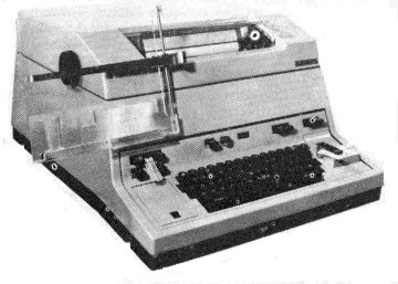 The
ITT Creed Model 444 (pronounced Four, forty-four) is a heavy-duty page-printing
teleprinter developed primarily to satisfy British Post Office requirements for
a Telex machine to CCITT standards. It can operate in either the simplex or the
duplex mode at speeds up to 75 Bauds, and is compatible with the majority of
teleprinters and circuits now in service. Each character is printed as soon as
it is received by type bars carried in a type basket which moves to and fro in
front of the stationary paper carriage. A range of additional optional features
is available to enable the machine to be used in specialised high-speed
telecommunications and data processing applications. The machine has been
designed to operate continuously for long periods and to function reliably with
the minimum of maintenance attention. With suitable lubricants and ribbon, it
will remain serviceable at temperatures within the range -25C to +50C. The Model
444 is basically a 5-unit, start-stop, two shift machine operating on
International Telegraph Alphabet No 2, no provision has been made for third
shift and there are no longer 6-unit machines.
The
ITT Creed Model 444 (pronounced Four, forty-four) is a heavy-duty page-printing
teleprinter developed primarily to satisfy British Post Office requirements for
a Telex machine to CCITT standards. It can operate in either the simplex or the
duplex mode at speeds up to 75 Bauds, and is compatible with the majority of
teleprinters and circuits now in service. Each character is printed as soon as
it is received by type bars carried in a type basket which moves to and fro in
front of the stationary paper carriage. A range of additional optional features
is available to enable the machine to be used in specialised high-speed
telecommunications and data processing applications. The machine has been
designed to operate continuously for long periods and to function reliably with
the minimum of maintenance attention. With suitable lubricants and ribbon, it
will remain serviceable at temperatures within the range -25C to +50C. The Model
444 is basically a 5-unit, start-stop, two shift machine operating on
International Telegraph Alphabet No 2, no provision has been made for third
shift and there are no longer 6-unit machines. Copyright George Hutchison, W7TTY & Bill Bytheway, K7TTY -- November 2011